
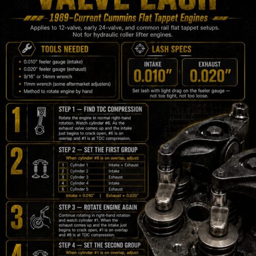
Setting Valve Lash (One-Pager)
Quick Summary
This guide explains how to set valve lash on 1989–current Cummins flat tappet engines, including 12-valve, early 24-valve, and common rail flat tappet setups. The engine is positioned at top dead center compression by watching the opposite cylinder enter valve overlap. Valve lash is then adjusted in two groups: When cylinder #6 is on overlap, adjust selected valves on cylinders 1–5. Rotate the engine until cylinder #1 is on overlap, then adjust the remaining valves on cylinders 2–6. Final lash specifications are: Intake: 0.010 inch Exhaust: 0.020 inch The feeler gauge should have a light drag after adjustment. This procedure does not apply to engines that still use factory hydraulic roller lifters.
Related Resources

Read Full Transcript / Details
Setting Valve Lash
1989–Current Cummins Flat Tappet Engines
Applies to 12-valve, early 24-valve, and common rail flat tappet setups.
Not for hydraulic roller lifter engines.
Tools Needed
0.010-inch feeler gauge for intake
0.020-inch feeler gauge for exhaust
9/16-inch or 14 mm wrench
11 mm wrench for some aftermarket adjusters
A method to rotate the engine by hand
Lash Specifications
Intake
0.010 inch
Exhaust
0.020 inch
Set lash with light drag on the feeler gauge—not too tight and not too loose.
Step 1 — Find TDC Compression
Rotate the engine in its normal right-hand direction.
Watch cylinder number 6. As the exhaust valve comes up and the intake valve just begins to crack open, cylinder number 6 is on valve overlap and cylinder number 1 is at top dead center on the compression stroke.
Step 2 — Set the First Group
When cylinder number 6 is on overlap, adjust:
Cylinder Valve
Cylinder 1 Intake and exhaust
Cylinder 2 Intake
Cylinder 3 Exhaust
Cylinder 4 Intake
Cylinder 5 Exhaust
Intake: 0.010 inch
Exhaust: 0.020 inch
Step 3 — Rotate the Engine Again
Continue rotating the engine in the normal right-hand direction and watch cylinder number 1.
When the exhaust valve comes up and the intake valve just begins to crack open, cylinder number 1 is on valve overlap and cylinder number 6 is at top dead center on the compression stroke.
Step 4 — Set the Second Group
When cylinder number 1 is on overlap, adjust:
Cylinder Valve
Cylinder 6 Intake and exhaust
Cylinder 5 Intake
Cylinder 4 Exhaust
Cylinder 3 Intake
Cylinder 2 Exhaust
Leave cylinder number 1 alone during this step.
Final Check
Confirm that:
All intake valves are set to 0.010 inch.
All exhaust valves are set to 0.020 inch.
The feeler gauge has light drag.
All locknuts are tightened.
The valve-train area is clear before reassembly.
Important
If your engine still uses factory hydraulic roller lifters, do not set valve lash.